customized
special solutions
B&B Control Blocks
Customized Special Solutions
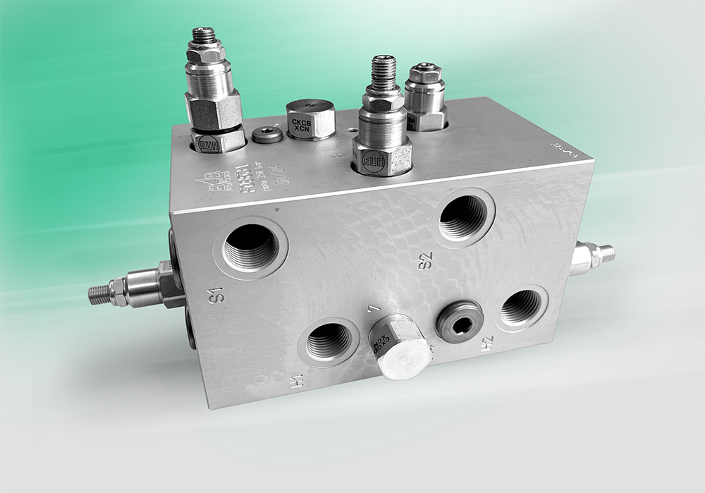
In industrial and mobile hydraulics, there is a demand for complex control systems that are space-saving, lightweight, functionally reliable, and cost-effective. B&B Fluidsysteme has made it its mission to fulfill these requirements.
Control blocks regulate hydraulic actuators, such as hydraulic cylinders or hydraulic motors. Furthermore, safety functions and logic circuits can be implemented.
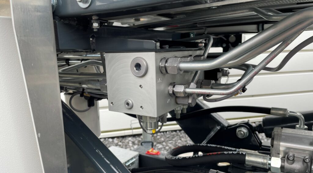
Starting from an aluminum or steel tube block, screw-in holes are drilled into which the valves are screwed. The connections between the valves are made by drilling. Valves with an ISO port pattern can be bolted onto the block, and inlets and outlets with connections can be bolted to the block. Manifold blocks for flange mounting on a cylinder or motor are also common practice.
The development of hydraulic control, the design of the blocks, as well as the manufacturing, assembly and testing of the finished products are integral parts of our value creation. Our range of services also includes small series production.
B&B Control Blocks
More often than you think!

Telescoping
Lifting cylinder control
Support extension
Support locking block
Basket leveling
Safely up!
B&B Advantages
What are the advantages of block technology?
Small Space Requirement
Since not every valve has to be piped in its own housing for switching, the result is usually a more compact solution.
Easy Installation
The valves only have to be screwed into the corresponding bores. Especially with more complex hydraulic systems, a clear solution is helpful.
Reduction of Leakage
Replacing pipe and hose lines as well as the associated screw connections with a valve block reduces the possible leakage.
Cost Advantage
Due to the reduction of the required individual components as well as lower assembly costs, a cost advantage often results, even with small quantities.
Project process
From inquiry to dispatch
Step
01

Inquiry & Requirements
In correspondence with the customer, the desired requirements are determined and the corresponding circuit is developed and an offer is created.
Step
02
CAD creation
The circuit is converted into a block design using 3D CAD program.
Here, attention is paid to a production-oriented design that meets the requirements.
Step
03

Customer coordination of the prototype
The customer receives a prototype drawing for coordination with his design and to be able to make necessary corrections.
Step
04
Order / Production
Upon receipt of the order, the prototype of the valve block is manufactured on a machining center, deburred, cleaned, and prepared for surface treatment.
Step
05
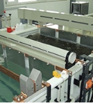
Finishing
Aluminum components are anodized. Steel components are chemically nickel-plated. Other processes can also be used on request.
Step
06
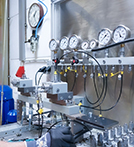
Assembly / Quality Assurance
The control block is equipped with all components and, if necessary, tested. For traceability, it is marked with the
delivery week.
Step
07
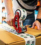
Shipping Preparation for Delivery
After assembly, the valve blocks are carefully packaged to protect them against contamination and transport damage on their way to the customer.
Step
08

Delivery – A Satisfied Customer
Decades of experience have shown that the products we supply function reliably and durably in customer applications.
